Building AGV Network Logic
Introduction to AGV Network Logic
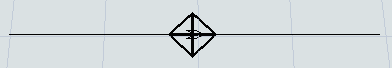
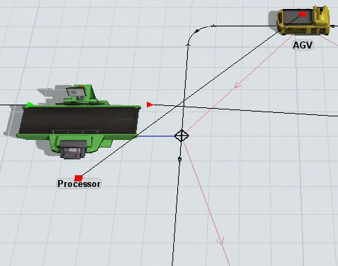
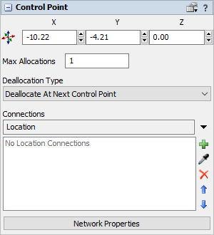
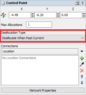
The following image shows an example of a control point on an AGV path:
In addition to the AGV process flow template, AGV control points are the key to creating the logic and functionality of AGV networks:
- AGVs need to be connected to control points in order to enter and exit the AGV network
- When an AGV passes over a control point, that control point can give the AGV instructions about which control point should be its next destination (a pick up point, a drop off point, another control point where the AGV will look for work, etc.)
- Fixed resources must be connected to control points in order to transport items through the AGV network
- Control points can affect traffic control and help prevent potential collisions or deadlocks
- If you are going to use elevators to transport AGVs to multiple floors, you'll need a combination of control points to handle that logic
Adding Control Points to a Path
To add a control point to a path:
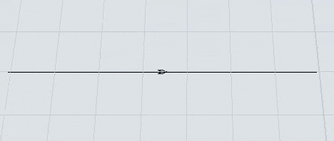
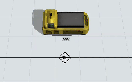
- In the Library under the AGV group, drag a Control Point into the model.
- Position the control point so that it is over an AGV path. When it connected to an AGV path, the control point will look like a diamond with crosshairs, as shown in the following image:
Connecting Fixed Resources to the AGV Network
When an item in a fixed resource needs to be transported via the AGV network, you need to associate that fixed resource with a specific control point on the network, so that AGVs will know how to navigate to the fixed resource on the network.
To connect a fixed resource to a control point:
- Press and hold the A key to enter connection mode. When you are in connection mode,
your mouse pointer will change to a plus sign with a chain link symbol next to it:

- Click the fixed resource you want to connect to a control point. You will notice as you move your mouse that a yellow line will appear between the object you clicked and your cursor.
- Hover over the control point so that it is highlighted. Click the control point to open a menu. Select Location. A blue line will appear to show that the fixed resource is now connected to the control point.
- Click the fixed resource to open its properties on the right. Under the
Output section, set up the Send To
Port property so that it sends items to the appropriate destination:
- You can use port connections to send the item to its destination. Make sure that the upstream fixed resource is connected to the downstream fixed resource with an input/output port connection (A-connect). Then set the port connection to use whatever flow logic your business system needs. See Overview of 3D Object Flows for more information.
- You can push the item to a list. Make sure that the downstream fixed resource(s) are set up to pull items from the list as well.
- Also under the Output section, check the Use
Transport box. In the box next to this checkbox, set up this property to assign
AGVs to transport the item to its destination:
- If you are using the AGV process flow template, you should select Use List and select the AGVWork list that is automatically generated when you use the AGV process flow template.
- If you are using a simple AGV network system with one AGV, use a center port connection (S-connect) to connect the fixed resource to the AGV.
- If you are using multiple AGVs, use a center port connection (S-connect) to connect the fixed resource to a dispatcher. Then, use input/output connections (A-connects) connect the dispatcher to all the AGVs in the system.
When a simulation runs, the fixed resource will hold the item until the AGV reaches the control point it is connected to. The item will immediately appear on the AGV once it has been transferred.
Connecting AGVs to the AGV Network
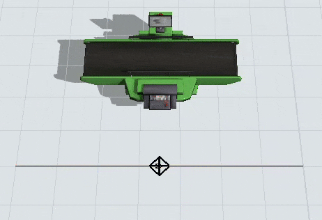
In order for an AGV to travel on an AGV path network, it needs to be connected as a Traveler AGV to a control point on the AGV network. Choose a control point that is on the main AGV network. It should be close to the area where you want the AGVs to enter.
To connect an AGV to a control point:
- Press and hold the A key to enter connection mode. When you are in connection mode,
your mouse pointer will change to a plus sign with a chain link symbol next to it:
- Click the AGV. You will notice as you move your mouse that a yellow line will appear between the object you clicked and your cursor.
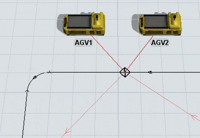
- Hover over the control point so that it is highlighted. Click the control point to open a menu. Select Traveler AGV. A red line will appear to show that the AGV is now connected to the control point. When you reset the model, the AGV will begin traveling from this control point.
- Repeat the previous steps to connect multiple AGVs to control points.
When you reset the simulation model, any AGVs that are connected to this control point will appear on that point. If multiple AGVs are connected to that point, they might overlap on that control point.
Control Point Connections
Control points are the basic building blocks of logic in an AGV network. They are both the "end points" of travel, as well as the "stepping stones" of AGV look-ahead allocation. Additionally, control points can be logically associated with each other, through control point connections. Control point connections are an incredibly powerful feature that makes it easier to drive the logic of an AGV model.
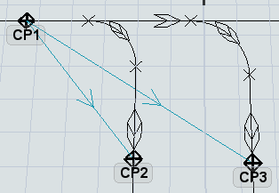
At its most basic level, a control point connection is just a named connection from a control point to another object or control point. A connection can be one-way or two-way, and a control point can have more than one connection of the same name. For example, a control point CP1 may have two DropoffPoints connections, to control points CP2 and CP3 respectively.
Control point connections, by themselves, do not have inherent, hard-coded meanings. In other words, creating the above-mentioned DropoffPoints connections from CP1 to CP2 and CP3 does not actually trigger any special internal logic of the AGV system. Simply making these connections will not change anything about the way your model runs.
However, when you decide to use a process flow like the AGV process flow template or the AGV elevator process flow, or if you decide to add AGV Offset Travel, you are giving meaning to various control point connections. For example, the AGV process flow defines specific meanings for the Location, PickupPoints, DropoffPoints, ParkPoints, LookForWork, and NextLookForWork connections. The AGV elevator process flow defines specific meanings for the ElevatorFloorCP, ElevatorRedirectCP, and ElevatorEntryCP connections.
Creating Control Point Connections in the 3D View
To create a control point connection:
- Press and hold the A key to enter connection mode. When you are in connection mode,
your mouse pointer will change to a plus sign with a chain link symbol next to it:
- Click the control point from which you want to originate the connection. You will notice as you move your mouse that a yellow line will appear between the object you clicked and your cursor.
- Hover over the control point that will become the end point of the connection, so that it is highlighted. Click the control point to open a menu. Select name of the control point connection you want to create.
Creating Control Point Connections in Properties
In some cases, the control points are geographically distant, such that is hard to make the connection in the 3D view. In this case, you can also create a control point connection through a control point's Properties pane.
- Click the control point from which you want to originate the connection.
- In Properties under Connections, press the drop-down and and select the name of the connection you want to add to, e.g. PickupPoints.
- Press the
 Add button and a popup will
appear.
Add button and a popup will
appear. - Navigate in the view to the desired control point you want to connect to, or type in the name of the control point in the search/filter control. Once you've found the target control point(s), click or lasso them so that they are highlighted in blue.
- Press Select.
Removing Control Point Connections
To remove a control point connection:
- Click the control point to select it.
- In Properties, find the Connections menu and select the type of connection you want to remove.
- In the box below this menu, click the name of the object to which you want to remove the connection.
- Click the Remove button
 to delete the connection.
Changing AGV Settings
After you've set up the basic logic of your AGV network, you might want to make changes to the way AGVs behave. You can customize the speed at which AGVs travel, their load capacity, their battery life cycle, the amount of time they take to load and unload items, etc. This section will discuss the different properties you can control and where to adjust those settings.
AGV Network Properties
The AGV network properties can be accessed either from the Toolbox (it shows up as AGV Network) or by clicking on an AGV path and clicking the Network Properties button in Properties.
Using the AGV network properties window, you can set the global speed for all AGVs on the AGV networks, their battery capacities and charging rates, their accumulation behavior, their deallocation behavior, and general visual settings. The following shows two of the more useful tabs on the AGV Network Properties window:
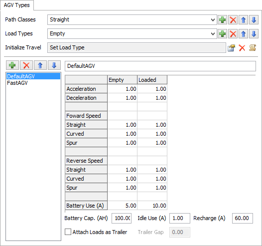
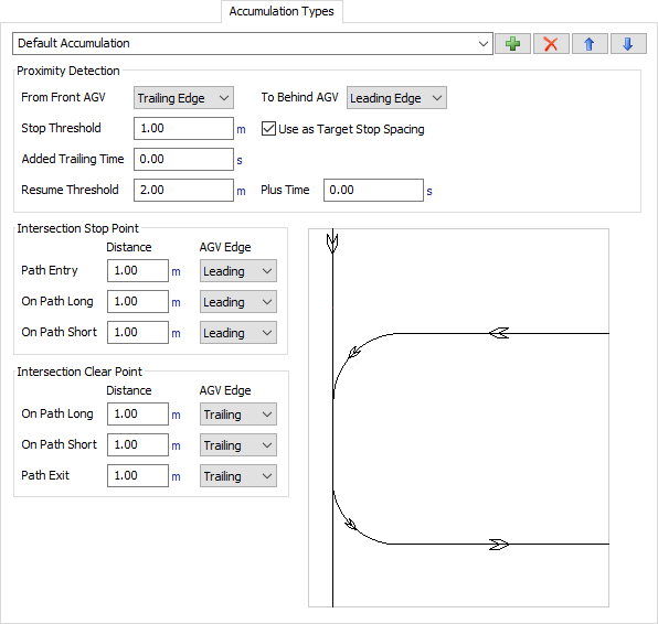
See AGV Network in the reference section for more information about these properties.
TaskExecuter Properties
If you click an AGV (which is technically the TaskExecuter object), it will open its properties where you can edit properties such as its capacity, etc. Note that the AGV network logic ignores the task executer's max speed, acceleration, and deceleration properties in favor of its own customized speed settings.
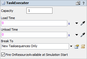
See The Task Executer Tab in the reference section for more information about these properties.
Preventing Collisions and Deadlocks
AGV networks have a sophisticated look-ahead mechanism that can avoid crashes by determining if the next control point on the path is available or not. If it is not available, the AGV will wait at its current control point.
A few key terms to be aware of:
- Allocation - When an AGV is traveling to or occupying a control point/area, that means the control point/area is allocated by the AGV. You could think of it as acquiring that control point so that it can't be acquired by other AGVs. You can set the maximum number of AGVs that may allocate a specific control point/area at a given time.
- Deallocation - When an AGV releases a control point so that it can be acquired by another AGV. You can set a control point to deallocate when an AGV reaches the next control point or you can set it to deallocate the control point after an AGV has passed over it. Or, you create your own rules for when control points and areas are deallocated using Deallocation Types
Control points act as "stepping stones" on the AGVs path. When an AGV arrives at a control point, say CP1, it will attempt to allocate ahead to the next control point, say CP2. If it cannot allocate CP2, then it will decelerate to stop at CP1, and wait until it can allocate CP2 before continuing on.
Control Areas
A control area acts as an additional allocation tool for restricting access to an entire area. As already mentioned, when an AGV arrives at a control point, it will allocate ahead to the next control point. If it must enter any control areas as part of its path to that control point, it must also allocate all of those control areas, then allocate the control point, before it can proceed forward. Note that if it cannot allocate all of the control areas as well as the control point itself, it will not allocate any of them. This helps to prevent deadlock.
By placing a control area around an area of your AGV network, you can prevent AGVs from colliding with each other. Control areas will restrict access to an area of the AGV network so that only a set number of AGVs can occupy that area at a time. By default, only one AGV can occupy the area at a time, but you can change the number of AGVs that can access the area in the control areas properties if needed.
If you run your simulation model and experience collisions or deadlocks, the issue is probably caused by how control points are being allocated and deallocated. This section will explain some of the methods to troubleshoot these kinds of problems.
Adding More Control Points
One simple solution to fixing deadlocks is to add more control points along an AGV path. Having more control points makes it so that AGVs have more opportunities to deallocate quickly.
Changing Deallocation Types
By default, control points are set to deallocate when the AGV reaches the next control point. You can change a control point's deallocation type to make it less strict:
- Click a control point to select it.
- In Properties click the Deallocation Type menu and select Deallocate When Past Current.
Adding Control Areas
To add a control area:
- In the Library in the AGV group, click Control Area to enter control area building mode.
- Place your cursor outside the top right corner of the portion of the AGV network where you want to add the control area. Click to begin drawing a control area box. Draw the control area box around the portion of the AGV network you want to restrict.
- Press Esc to exit control area building mode.
- Click the control area and use the sizer arrows if you need to resize the control area.
- While the newly added control area is selected, you can edit its properties in the Properties panel if needed.