Task 1.4 - Add A* Navigation
Task Overview
In this tutorial task, you'll learn how to use A* navigation to prevent the patients and staff members from walking through objects and the floor plan walls. With A* navigation, you can designate where the patients and staff members can walk and where they cannot.
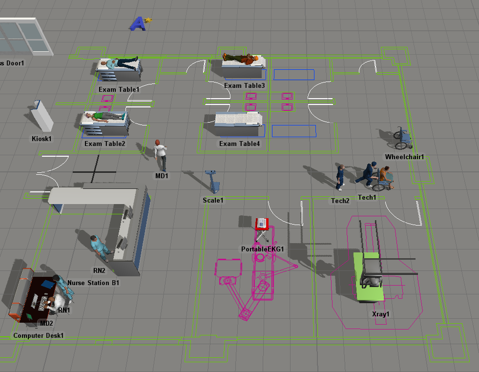
When you're finished, your simulation model should look similar to the following image:
Step 1 Add A* Dividers
In this step, you'll add some A* dividers to the model. A* navigation is a tool that calculates the shortest path a person can use when walking from one object to another. You can place dividers to prevent a person from walking through an area that they shouldn't walk through (such as walking through an object or the wall of a room). The A* Navigator will take these dividers into account when calculating the best path for a person to travel. See Working With A* Navigation for more information.
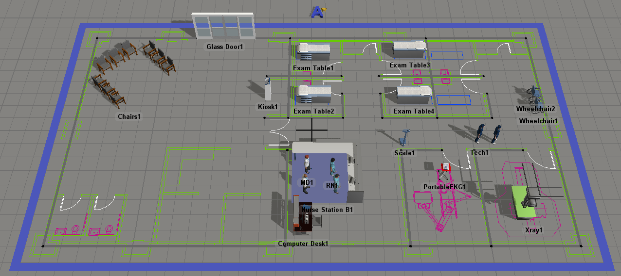
When you're finished adding the dividers, the model will look similar to the following image:
To add A* dividers:
- Make sure the 3D model is open and active. In the Library under the A* Navigation group, drag a Grid object into the model.
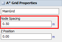
- Click the A* Grid (the large blue bar that surrounds the A* dividers) to select it.
- In Properties in the Node Spacing box, delete the
current number and type
0.50instead. Notice that the dividers and grid lines will become smaller. - Use the red sizer arrows to resize the grid around the floorplan.
- Make sure the 3D model is open and active. In the Library under the
A* Navigation group, click a
Divider object to enter Create Dividers mode. Your mouse
pointer will change to the Dividers icon
 to show that you are in Create Dividers
mode.
to show that you are in Create Dividers
mode. - Find the position in your simulation model where you want to place the beginning corner of a divider. When you click that position in the model and start moving the mouse pointer in a different direction, you'll notice that it begins creating a divider. Reposition the mouse pointer until the divider's end is at the approximate length, angle, and radius you want it to be relative to the start. Click the mouse again to finish creating the divider. Press Esc to exit Create Divider mode.
- These dividers will act as walls in the simulation model. Start by creating the outer walls on the floor plan (the ones surrounding the whole building). If you need to move or resize a divider, click the end points and drag them to a different position.
- Notice that when you added the dividers, an A* Navigator was automatically added in the center of your simulation model. (It looks like a blue A with a golden star next to it.) Drag the A* Navigator to a different area, placing it somewhere outside the floor plan.
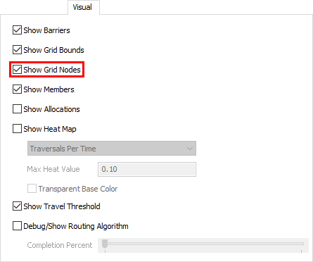
- Before adding dividers to the interior walls of the floor plan, double-click the A* Navigator to open its properties window. On the Visual tab, check the Show Grid Nodes checkbox. Click the OK button to save changes and close the window.
- Add more dividers for the interior walls of the building. Don't worry about putting the dividers exactly over the floor plan's walls. It's more important to try to put dividers in between the yellow A* grid lines if possible. These dividers will prevent movement from one point on the grid to another so it will work better if placed in between the grid rather than over it.
- Now that you've added dividers, you don't need the yellow gridlines any more. Double-click the A* Navigator to open its properties window. On the Visual tab, uncheck the Show Grid Nodes checkbox. Click the OK button to save changes and close the window.
Now that you've added A* dividers, it's time to add the 3D objects in the model to the A* navigation system. You'll add the objects in the next step.
Step 2 Connect 3D Objects to the A* Navigator
In this step, you'll connect most of the model's objects to the A* Navigator. By connecting location and prop objects to the A* system, it creates a small area of space around the objects that staff and patients will not be able to walk through. Connecting staff members to the A* system tells them to use A* for navigating around the model. You'll also learn how to check 3D object's travel thresholds in order to prevent any strange behavior when the 3D objects are using the A* navigation system.
To connect the 3D objects to the A* Navigator:
- Press and hold the A key to enter connection mode. When you are in connection mode,
your mouse pointer will change to a plus sign with a chain link symbol next to it:

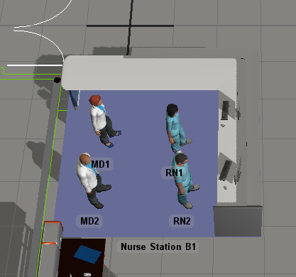
- Once you are in connection mode, click the A* Navigator. Click Nurse Station B1 to create a connection between the two objects.
- These next steps will demonstrate another method for adding members to the A* navigation system. Double-click the A* Navigator to open its properties window.
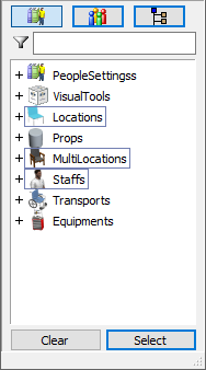
- On the Setup tab in the Members group, make sure that All Members is selected as the current member view.
- Click the Add button
 to open a menu of all the objects in the
model organized by their type.
to open a menu of all the objects in the
model organized by their type. - Click the Locations, Multilocations, and Staff categories. Then click the Select button. Notice that all the objects of those types now appear in the members list.
Step 3 Adjust for Travel Threshold
In this step, you'll display the travel threshold for several object in the model and adjust their position accordingly. The Show Travel Threshold checkbox that we use in this step is a visual display of the logic that A* uses under the hood.
To show object travel thresholds and adjust for them:
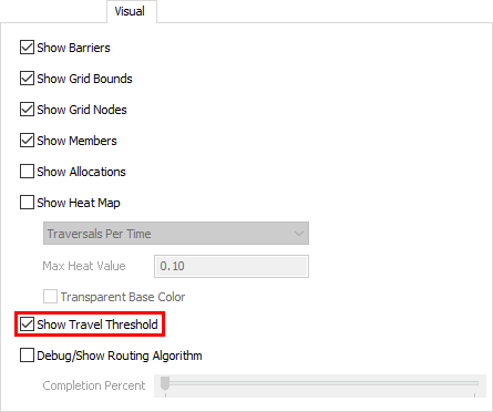
- Double-click the A* Navigator to open its properties window. On the Visual tab, check the Show Travel Threshold checkbox. Click the OK button to save changes and close the window.
- Click the ExamTable1 object to select it. Notice that you can now see the object's travel threshold, represented by several red and blue dots surrounding the object.
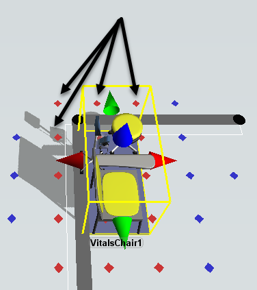
- Check to ensure that the none of the red travel threshold dots go beyond the dividers. (It is fine if the blue dots extend beyond the dividers.) For example, the following image shows a chair's red travel threshold that extends past a divider:
- Drag the ExamTable so that it is a little further away from the divider and none of the red travel thresholds extend beyond the divider. Be aware that there will also not be any problems if the red travel thresholds are exactly inside a divider.
- Repeat the previous steps with all of the Exam Tables to ensure their red travel threshold dots do not extend beyond each room's walls.
- If you would like to turn off the visual guides for the A* Navigation system, double-click the A* Navigator to open its properties window. On the Visual tab, clear all the checkboxes.
Save, then reset and run the simulation model:
Now when you run the model, the patients and the RNs no longer walk through objects or walls. Notice that the RN walks around the desks and the walls in the floor plan while traveling to the patient vitals area with the patient.
Conclusion
Up to this point, you've created a simulation model of a health care clinic in which a patient completes all the steps in their flow. In the next tutorial task, we'll look at how to give staff tasks independent of a patient's flow. Continue on to Tutorial Task 1.5 - Create Independent Tasks.