Creating Custom Flow Items
Importing Custom 3D Flow Items
Before reading this section, you might want to read Creating and Importing Custom 3D Objects for some general tips and tricks about working with custom 3D objects. It also includes suggestions about third party software and inexpensive 3D object services.
To import a custom 3D flow item:
- In the Flow Item Bin, click the Add button
 on the toolbar to open a flow item.
 - Select the type of flow item you want to create from the menu. If you are unsure of what type you should create, select Basic FlowItem. (See Types of Flow Items for more information about the types of flow items.)
- In Quick Properties under General Properties, use the first box to change the name of your flow item to something more descriptive.
- Click the arrow next to the Shape box
 to open a menu. Select
Browse.
to open a menu. Select
Browse. - Navigate to the location of the 3D file on your computer. Then select Open.
- The custom 3D shape will appear in the preview window. You can modify the shape's size and rotation in the preview window or using the other properties in Quick Properties.
Key Concepts About Flow Item Shape Frames
You can use flow item shape frames to change the appearance of the flow item as it moves through various stages or stations in your simulation model.
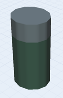
For example, imagine you want to simulate a bottling facility. You have four different flow items objects to represent the bottle at different stages. An empty bottle:
![]()
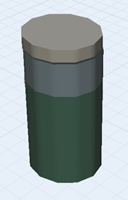
A filled bottle:
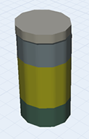
A bottle that has been capped:
A bottle that has been labeled:
To create a flow item that can have different visual appearances, you'd use each object as a different shape frame on the same flow item. You'd import the empty bottle to act as the base frame and add three additional shape frames for the other three shapes. In the 3D model, you would use triggers or Process Flow activities to change the shape frame at various points in the simulation model, as shown in the following image:
Adding Shape Frames
To add shape frames to a flow item:
- Create a custom flow item using the steps outlined in Importing Custom 3D Flow Items.
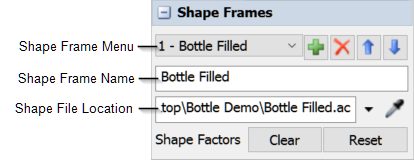
- In the flow item's Quick Properties under
Shape Frames, click the Add
button to add a new shape frame.
- In the Shape Frame Name box, type a descriptive name for this shape frame.
- Click the arrow next to the Shape Frame Box and select Browse.
- Navigate to the location of the 3D file on your computer. Then select Open.
- The custom 3D shape will appear in the preview window.
- Repeat steps 2-6 for additional shape frames.
Using Shape Frames in the 3D Model
After adding the logic that changes shape frames, you'll need to add the shape frames to the 3D model. First, make sure that the Source or Create Object activity will add the custom flow item to the 3D model during a simulation run. (See Getting Flow Items into a 3D Model for more information.)
After you've added the flow item to the 3D model, you can change the flow item's shape frame after it passes through another object in the 3D model, such as a processor. You can do this by setting the object's trigger to change the shape frame:
- Click on the 3D object that will change the flow item's shape frame (such as a processor) to open its properties on the right.
- Under the Triggers section, click the
Add button to
add the trigger that will change the flow item. For example, you could add an On Exit or
On Process Finish trigger.
- Click the Add button
next to the newly added trigger to open a
menu. Point to Visual, then select
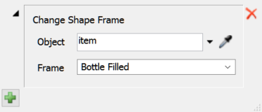
Change Shape Frame to open the Change
Shape Frame pick list.
- Click the arrow next to the Object box to open a menu. Select item.
- Click the Frame menu and select the name of the shape frame you want to use.
Alternatively, you could use a Change Visual process flow activity. See Overview of the Process Flow Interface for more information about the Process Flow tool.