The Flow Gauge Panel
The Flow Gauge panel is shown only for flow gauge objects.
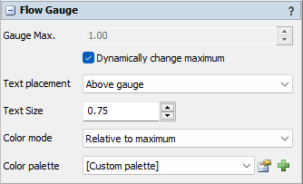
The following properties are on the Flow Gauge panel:
Gauge Max.
The maximum flow rate (the "100%") the dial can show. If the Gauge Max. is set to Dynamically change maximum the gauge will automatically set a maximum value to the smallest power of 10 above the maximum flow rate seen so far. If at any point during the simulation the maximum flow rate exceeds the gauge maximum, the maximum will be adjusted upwards.
If you disable the option Dynamically change maximum the dial will only move for flow rates between zero and the indicated maximum. If the flow rate through the gauge is larger, the dial will rotate to the maximum value.
Text placement
This setting determines where the label with the current flow rate is placed, relative to the gauge. The three options are shown in the image below.
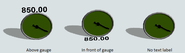
- Above gauge - The text label is shown above the dial, in the same plane as the gauge.
- In front of gauge - The text label is shown in front of the dial, perpendicular to the gauge (normally in the same plane as the model floor).
- No text label - The flow rate label is not shown, only the dial indicates the current flow.
Text size
The text size of the text label.
Color mode
The gauge can dynamically change color to provide additional visual information about the current flow. The following options are available.
- Fixed color - The flow gauge dial will be drawn using the object color set in the Visual panel, and will not dynamically change.
- Relative to maximum -
The flow gauge will dynamically change its color depending on the current flow rate relative to the maximum.
The color palette (see below) should be a gradient palette with values between 0 and 1 (or a little more than 1, if the
gauge maximum is set to a fixed value and you expect that the actual flow rate can be larger).
For example, if the (static or dynamic) gauge maximum is 200 and the actual flow is 150, then the flow gauge will calculate the relative value to be 75%. Based on the color palette above, it will change its dial to a color halfway between orange and green, corresponding to a value of 0.75 in the color palette.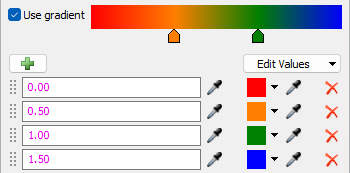
- By absolute rate -
The flow rate will dynamically change its color depending on the actual current flow rate. The color palette (see below)
should be a gradient palette with values between 0 and the expected maximum flow.
For example, if the actual flow is 750, then the flow gauge will change its dial to a color halfway between green and blue, regardless of the (static or dynamic) maximum of the flow gauge.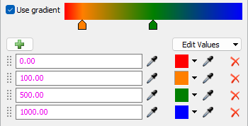
Color palette
When the Color mode is not set to Fixed color the color palette determines the dynamically chosen color for the gauge. The Color mode options above describe which values are expected for the color palette.
The dropdown allows any global Color Palette in the toolbox to be selected. In addition there is an option Custom palette that will use a color palette unique to this particular flow gauge. The properties button to the right of the selection box will open a popup where the color palette can be edited, whether it's global or local. The add button to the right of the selection box creates a new global Color Palette in the toolbox. In addition to the predefined color palettes built-in to FlexSim, FloWorks provides a "Red to Green" option that varies from red (at zero) through orange to green (at one) and blue (above one) which is suitable to be used with the default color mode of Relative to maximum as described above.