Building AGV Network Logic
Introduction to AGV Network Logic
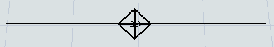
The following image shows an example of a control point on an AGV path:
In addition to the AGV process flow template, AGV control points are the key to creating the logic and functionality of AGV networks:
- AGVs need to be connected to control points in order to enter and exit the AGV network
- When an AGV passes over a control point, that control point can give the AGV instructions about which control point should be its next destination (a pick up point, a drop off point, another control point where the AGV will look for work, etc.)
- Fixed resources must be connected to control points in order to transport items through the AGV network
- Control points can affect traffic control and help prevent potential collisions or deadlocks
- If you are going to use elevators to transport AGVs to multiple floors, you'll need a combination of control points to handle that logic
Adding Control Points to a Path
To add a control point to a path:
- In the Library under the AGV group, drag a Control Point into the model.
- Position the control point so that it is over an AGV path. When it connected to an AGV path, the control point will look like a diamond with crosshairs, as shown in the following image:
Connecting Fixed Resources to the AGV Network
When an item in a fixed resource needs to be transported via the AGV network, you need to associate that fixed resource with a specific control point on the network, so that AGVs will know how to navigate to the fixed resource on the network.
To connect a fixed resource to a control point:
- Press and hold the A key to enter connection mode. When you are in connection mode,
your mouse pointer will change to a plus sign with a chain link symbol next to it:

- Click the fixed resource you want to connect to a control point. You will notice as you move your mouse that a yellow line will appear between the object you clicked and your cursor.
- Hover over the control point so that it is highlighted. Click the control point to open a menu. Select Location. A blue line will appear to show that the fixed resource is now connected to the control point.
- Click the fixed resource to open its properties on the right. Under the
Output section, set up the Send To
Port property so that it sends items to the appropriate destination:
- You can use port connections to send the item to its destination. Make sure that the upstream fixed resource is connected to the downstream fixed resource with an input/output port connection (A-connect). Then set the port connection to use whatever flow logic your business system needs. See Overview of 3D Object Flows for more information.
- You can push the item to a list. Make sure that the downstream fixed resource(s) are set up to pull items from the list as well.
- Also under the Output section, check the Use
Transport box. In the box next to this checkbox, set up this property to assign
AGVs to transport the item to its destination:
- If you are using the AGV process flow template, you should select Use List and select the AGVWork list that is automatically generated when you use the AGV process flow template.
- If you are using a simple AGV network system with one AGV, use a center port connection (S-connect) to connect the fixed resource to the AGV.
- If you are using multiple AGVs, use a center port connection (S-connect) to connect the fixed resource to a dispatcher. Then, use input/output connections (A-connects) connect the dispatcher to all the AGVs in the system.
When a simulation runs, the fixed resource will hold the item until the AGV reaches the control point it is connected to. The item will immediately appear on the AGV once it has been transferred.
Connecting AGVs to the AGV Network
In order for an AGV to travel on an AGV path network, it needs to be connected as a Traveler AGV to a control point on the AGV network. Choose a control point that is on the main AGV network. It should be close to the area where you want the AGVs to enter.
To connect an AGV to a control point:
- Press and hold the A key to enter connection mode. When you are in connection mode,
your mouse pointer will change to a plus sign with a chain link symbol next to it:
- Click the AGV. You will notice as you move your mouse that a yellow line will appear between the object you clicked and your cursor.
- Hover over the control point so that it is highlighted. Click the control point to open a menu. Select Traveler AGV. A red line will appear to show that the AGV is now connected to the control point. When you reset the model, the AGV will begin traveling from this control point.
- Repeat the previous steps to connect multiple AGVs to control points.
When you reset the simulation model, any AGVs that are connected to this control point will appear on that point. If multiple AGVs are connected to that point, they might overlap on that control point.
Control Point Connections
Control points are the basic building blocks of logic in an AGV network. They are both the "end points" of travel, as well as the "stepping stones" of AGV look-ahead allocation. Additionally, control points can be logically associated with each other, through control point connections. Control point connections are an incredibly powerful feature that makes it easier to drive the logic of an AGV model.
At its most basic level, a control point connection is just a named connection from a control point to another object or control point. A connection can be one-way or two-way, and a control point can have more than one connection of the same name. For example, a control point CP1 may have two DropoffPoints connections, to control points CP2 and CP3 respectively.
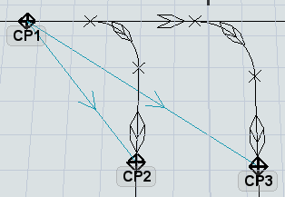
Control point connections, by themselves, do not have inherent, hard-coded meanings. In other words, creating the above-mentioned DropoffPoints connections from CP1 to CP2 and CP3 does not actually trigger any special internal logic of the AGV system. Simply making these connections will not change anything about the way your model runs.
However, when you decide to use a process flow like the AGV process flow template or the AGV elevator process flow, or if you decide to add AGV Offset Travel, you are giving meaning to various control point connections. For example, the AGV process flow defines specific meanings for the Location, PickupPoints, DropoffPoints, ParkPoints, WorkForwarding, and NextWorkPoint connections. The AGV elevator process flow defines specific meanings for the ElevatorFloorCP, ElevatorRedirectCP, and ElevatorEntryCP connections.
Creating Control Point Connections in the 3D View
To create a control point connection:
- Press and hold the A key to enter connection mode. When you are in connection mode,
your mouse pointer will change to a plus sign with a chain link symbol next to it:
- Click the control point from which you want to originate the connection. You will notice as you move your mouse that a yellow line will appear between the object you clicked and your cursor.
- Hover over the control point that will become the end point of the connection, so that it is highlighted. Click the control point to open a menu. Select name of the control point connection you want to create.
Creating Control Point Connections in Properties
In some cases, the control points are geographically distant, such that is hard to make the connection in the 3D view. In this case, you can also create a control point connection through a control point's Properties pane.
- Click the control point from which you want to originate the connection.
- In Properties under Connections, press the drop-down and and select the name of the connection you want to add to, e.g. PickupPoints.
- Press the
 Add button and a popup will
appear.
Add button and a popup will
appear. - Navigate in the view to the desired control point you want to connect to, or type in the name of the control point in the search/filter control. Once you've found the target control point(s), click or lasso them so that they are highlighted in blue.
- Press Select.
Removing Control Point Connections
To remove a control point connection:
- Click the control point to select it.
- In Properties, find the Connections menu and select the type of connection you want to remove.
- In the box below this menu, click the name of the object to which you want to remove the connection.
- Click the Remove button
 to delete the connection.
Changing AGV Settings
After you've set up the basic logic of your AGV network, you might want to make changes to the way AGVs behave. You can customize the speed at which AGVs travel, their load capacity, their battery life cycle, the amount of time they take to load and unload items, etc. This section will discuss the different properties you can control and where to adjust those settings.
AGV Network Properties
The AGV network properties can be accessed either from the Toolbox (it shows up as AGV Network) or by right-clicking on an AGV path and choosing AGV Network Properties.
Using the AGV network properties window, you can set the global speed for all AGVs on the AGV networks, their battery capacities and charging rates, their accumulation behavior, their deallocation behavior, and general visual settings. The following shows two of the more useful tabs on the AGV Network Properties window:
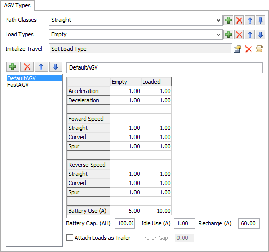
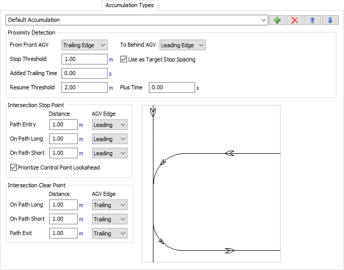
See AGV Network in the reference section for more information about these properties.
TaskExecuter Properties
If you click an AGV (which is technically the TaskExecuter object), it will open its properties where you can edit properties such as its capacity, etc. Note that the AGV network logic ignores the task executer's max speed, acceleration, and deceleration properties in favor of its own customized speed settings.
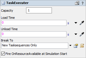
See The Task Executer Tab in the reference section for more information about these properties.
Understanding Allocation Behavior and Terminology
AGV networks have a powerful look-ahead mechanism that can avoid crashes and provide sophisticated traffic control. FlexSim provides several mechanisms for configuring these behaviors.
Control points act as "stepping stones" on the AGVs path. When an AGV arrives at a control point, say CP1, it will attempt to allocate ahead to the next control point, say CP2. If it cannot allocate CP2, then it will decelerate to stop at CP1, and wait until it can allocate CP2 before continuing on. This is independent of how far separated CP2 is from CP1 on the network. In other words, when default settings are used, control points are the only points where AGVs can stop on the network. They will not continue from one control point to the next until they have allocated that next control point, no matter how far ahead it is. As such, they may look very far ahead in their travel path to allocate the next control point.
Preventing Collisions and Deadlocks
In FlexSim, simple control point allocation/deallocation is the default mechanism by which AGVs avoid collisions with each other. The reasoning for using this as the default behavior is guided by a 'collision avoidance guarantee'.
Collision Avoidance Guarantee
There are a set of rules that, if followed, will guarantee that AGV collisions will never happen in your model. These are:
| Rule | How to Follow | |
|---|---|---|
| Rule 1 | An AGV must allocate a control point before traveling to it | Automatically guaranteed by internal AGV logic |
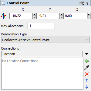
| Rule 2 | Only one AGV can allocate a control point at a time | Leave each control point's Max Allocations property as 1 |
| Rule 3 | An AGV will not deallocate a control point until it is completely past that control point | Use the default 'Deallocate at Next Control Point' Deallocation Type, and follow Rule 4 |
| Rule 4 | All control points are spaced at least one AGV length away from each other | Properly lay out control points in the model |
| Rule 5 | AGV paths are sufficiently spaced so that AGVs traveling on one path can never collide with AGVs traveling on a completely separate path | Properly lay out paths in the model |
| Rule 6 | AGVs can only stop at control points | Do not use accumulation, preemption, or customized AGV travel behavior |
In situations where following all of these rules is possible, you get collision avoidance for free. Just create your control points, path network, AGVs, and dispatching logic. Run the model and you will get collision avoidance automatically.
Relaxing the Rules
In reality, however, some of these rules may need to be relaxed in order get the behavior you want or to make model-building easier. For example, you may have long sections of path in your model. If you put control points too far apart on those paths, then FlexSim's default allocation algorithm (Rules 1 and 2) will cause low throughput because AGVs must allocate far ahead, causing large gaps where there are no AGVs. To fix this:
- Place many more control points along the path. This would ensure that you're still following all rules above, but it takes more work because you have to create a lot of control points.
- Instead, relax Rule 2 above by increasing the number of AGVs that can allocate a control point that is on a long section of path, and instead use accumulation to ensure AGVs do not run over each other while on that path.
Additionally, intersections can by themselves be an inherent violation of Rule 5, and you may need to use control areas and/or accumulation to prevent collisions at intersections. Also, you may want to actually use the features that would break Rule 6. Finally, following Rules 1-6 does not guarantee against deadlock, so you'll still need to ensure deadlock prevention.
The reality is that, while these rules are a good starting point to think about as you build your model, they are in the end just guidelines, and you'll likely need to implement strategies that do not strictly follow Rules 1-6. Nevertheless, it's important to understand that relaxing one or more of these rules will negate the collision avoidance guarantee. Consequently, in those situations you may need to provide some other mechanism for preventing collisions. FlexSim provides many mechanisms for achieving this, such as control areas, accumulation, mutual exclusion using process flow, or even proximity detection with the Agent module. Further, you can mix and match strategies. In some areas of your model you can follow all of the rules and thus get collision avoidance for free, while in other areas, you can relax some rules and implement supplemental collision avoidance mechanisms.
This section will explain strategies for fixing various problems associated with deadlock and collision avoidance.
Adding More Control Points
As mentioned above, you can add more control points to your network. This can increase overall throughput, but also serves to prevent deadlock. Having more control points makes it so that AGVs have more "stepping stones" that they can go to in getting to their destination. This helps prevent the creation of allocation cycles required for deadlock.
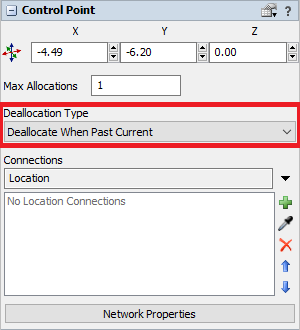
Changing Deallocation Types
By default, control points are set to deallocate when the AGV reaches the next control point. You can change a control point's deallocation type to make it deallocate earlier, freeing more control points to be re-allocated:
- Click a control point to select it.
- In Properties click the Deallocation Type menu and select Deallocate When Past Current.
Adding Control Areas
A control area can be useful for avoiding deadlock, or if you need to relax one or more of Rules 2-6, but still need to avoid collisions. To add a control area:
- In the Library in the AGV group, click Control Area to enter control area building mode.
- Place your cursor outside the top right corner of the portion of the AGV network where you want to add the control area. Click to begin drawing a control area box. Draw the control area box around the portion of the AGV network you want to restrict.
- Press Esc to exit control area building mode.
- Click the control area and use the sizer arrows if you need to resize the control area.
- While the newly added control area is selected, you can edit its properties in the Properties panel if needed.
Managing Two-Way Paths
If your system includes two-way paths, then you should find a way to prevent AGVs from traveling in opposite directions on the path at the same time. Two AGVs going in opposite directions on the same path at the same time will almost always create a deadlock situation. Control areas can be used here to implement such restrictions.