Connecting to PLCs of MITSUBISHI product family using MX Component
Overview
Emulation module makes FlexSim able to connect to PLCs (physical or simulated) of Mitshubishi MELSEC family using the MX Component.
Mitsubishi
MX Component is a control library that enables communication from
a PC to a programmable controller and motion controller regardless of
communication protocol.
This control library is not provided with FlexSim and it must be
purchased from Mistubishi and installed.
Several steps are necessary to build a fully functional example:
- Create a GX Works3 project.
- Write the PLC code, compile it and download it to a physical PLC or to the GX Simulator3.
- Download the project to the PLC
- Use the GX Simulator3.
- Configure the MX Component Communication Setting Utility
- Prepare a FlexSim model and connect it to the PLC.
- Test the model.
Step 1 Create a GX Woks3 project
In this tutorial GX Works3 will be used.
Following steps are to create create and configure a project to connect to a physical PLC or to use the simulator (GX Simulation3).
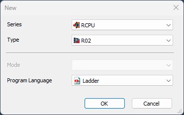
Open GX Works3 and select Project → New from
the menu bar.
Select the PLC Series, Model (this tutorial use a iQ-R R02 CPU) and
Ladder as programming language:
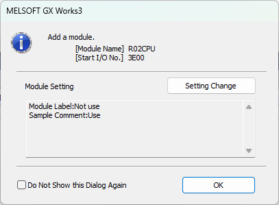
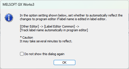
A new empty project will be created:
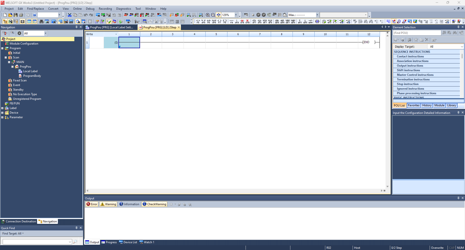
Before continue save the project.
The following steps are to configure a connection to a physical PLC.
These steps can be skipped if you would like only use the GX Simulator3.
If so, jump to Step 2 - Write the PLC code.
Select Online → Current Connection Destination to configure and test the communication with the PLC.
Select Ethernet Board for the PC side I/F and PLC Module for the PLC side I/F
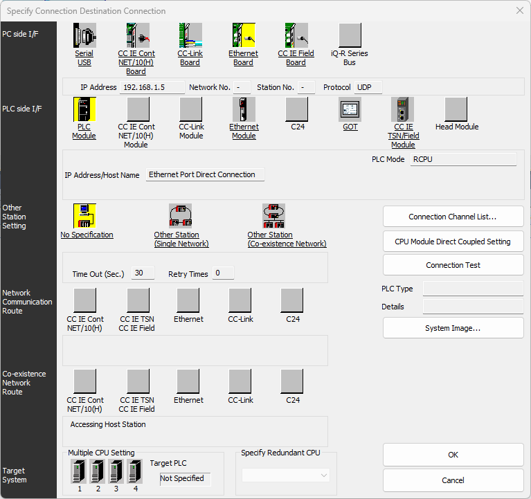
Press CPU Module Direct Coupled Setting button and select Ethernet interface to be used to reach the PLC:
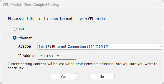
Press Yes and confirm subsequent forms.
Then press Connection Test to verify the connection with the PLC:
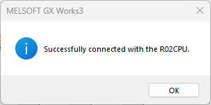
Press Ok to close the Current Connection Destination
Now proceed with the project's configuration.
The following steps are required to connect either a physical PLC or a simulator.
From the Navigation tree select Module Parameters:
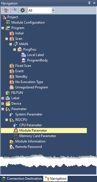
Set the IP Address / Sub-net Mask / Default gateway to be used for the PLC.
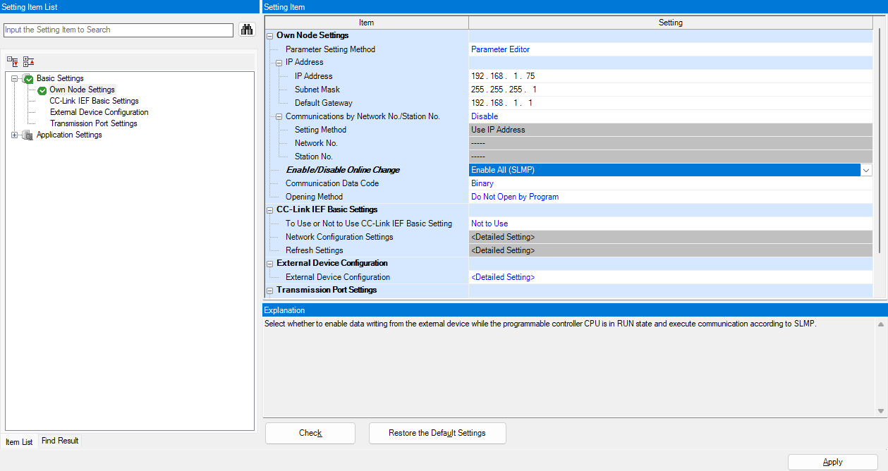 Moreover set the Enable/Disable
Online Change option to Enable All (SLMP).
Moreover set the Enable/Disable
Online Change option to Enable All (SLMP). Do a mouse double click on <Detailed Setting> of the External Configuration Option.
The Ethernet Configuration form will be shown:
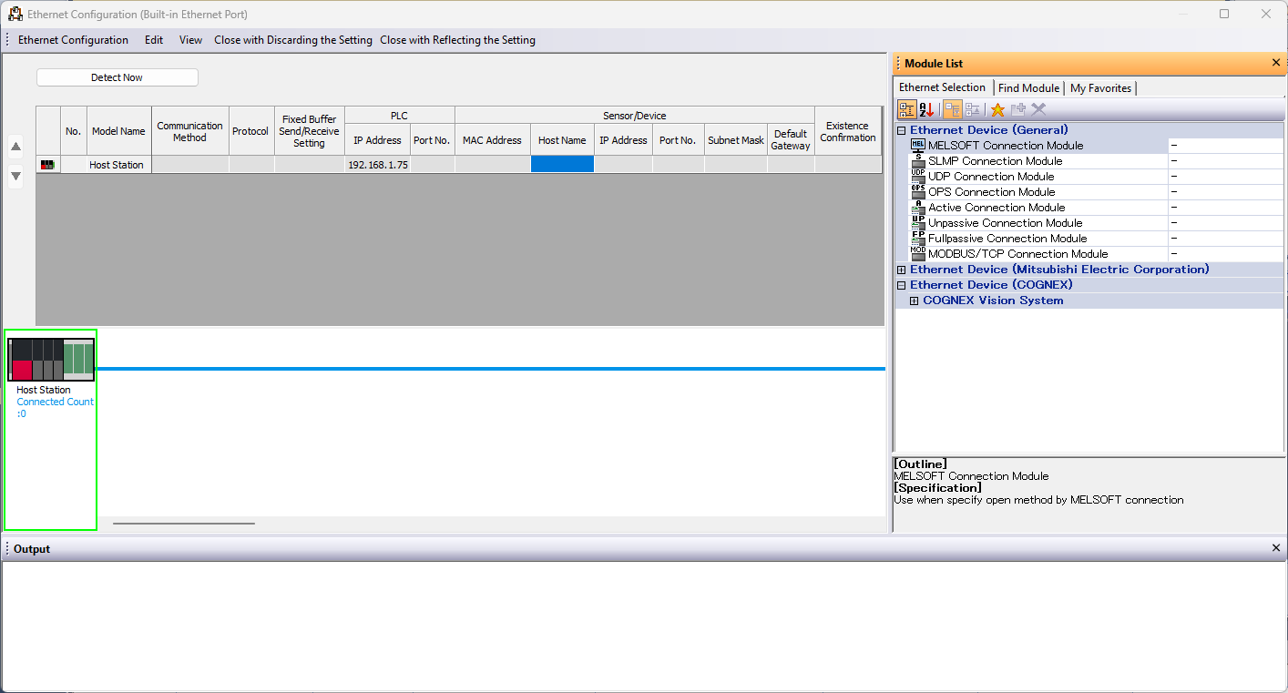
Expand the Ethernet Device (General) on the right and drag from the list a MELSOFT Connection Module on the blue line at the bottom:
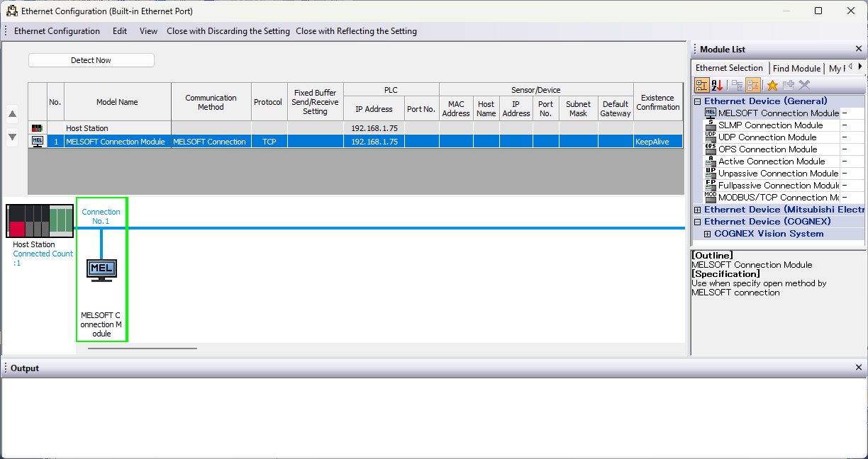
Now the project is configured.
Step 2 Write the PLC code
Write the PLC code, compile it and download it to a PLC.In this tutorial we will realize a simple delayer where a digital input is delayed in output of 1 seconds.
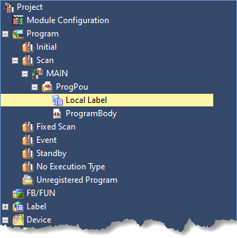
Once the project is created and configured, from the Navigation tree double click the Device Label:
Then type TIMER1 into column Label Name of row 1, press the "…" ,select Function Block from the Type Category group and from the Data Type list select TON.
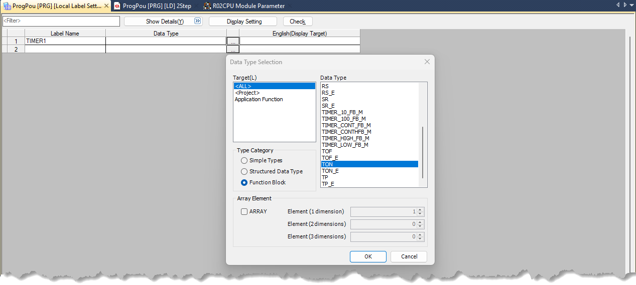
Then press Ok to confirm selection and then close the Local Label page.
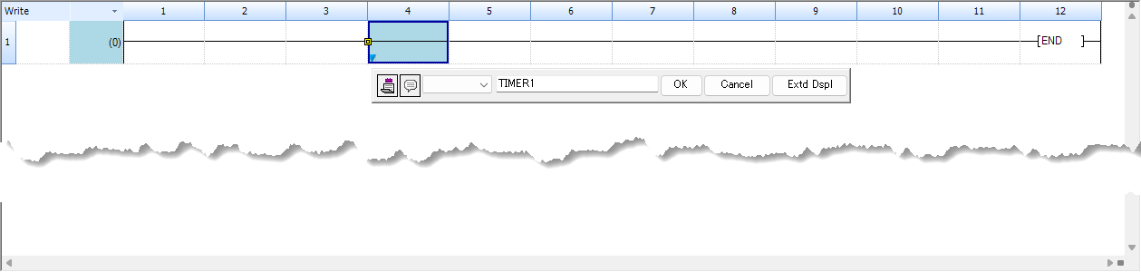
Now start write the ladder program.
From the Navigation tree select ProgramBody, the ladder editor will be show.
Do a mouse double click at row 1 column 4 and enter TIMER1 in the value field. Then press OK.
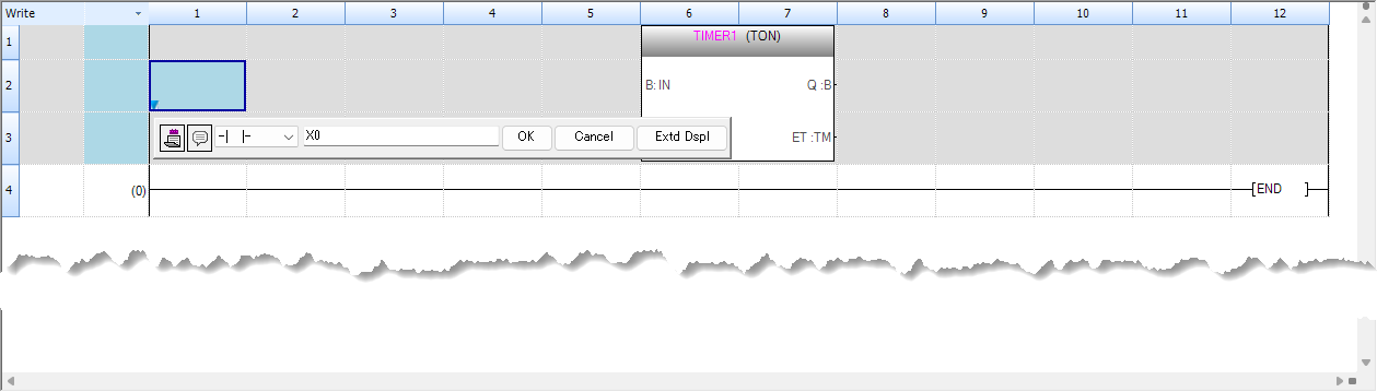
The timer will be added. Select row 2 and col 1 then press F5 and write X0 in the value field:
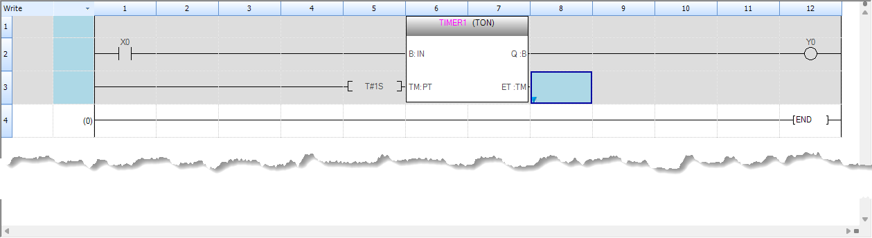
Complete the ladder logic as follow:
When completed the project need to be compiled and downloaded to the PLC.
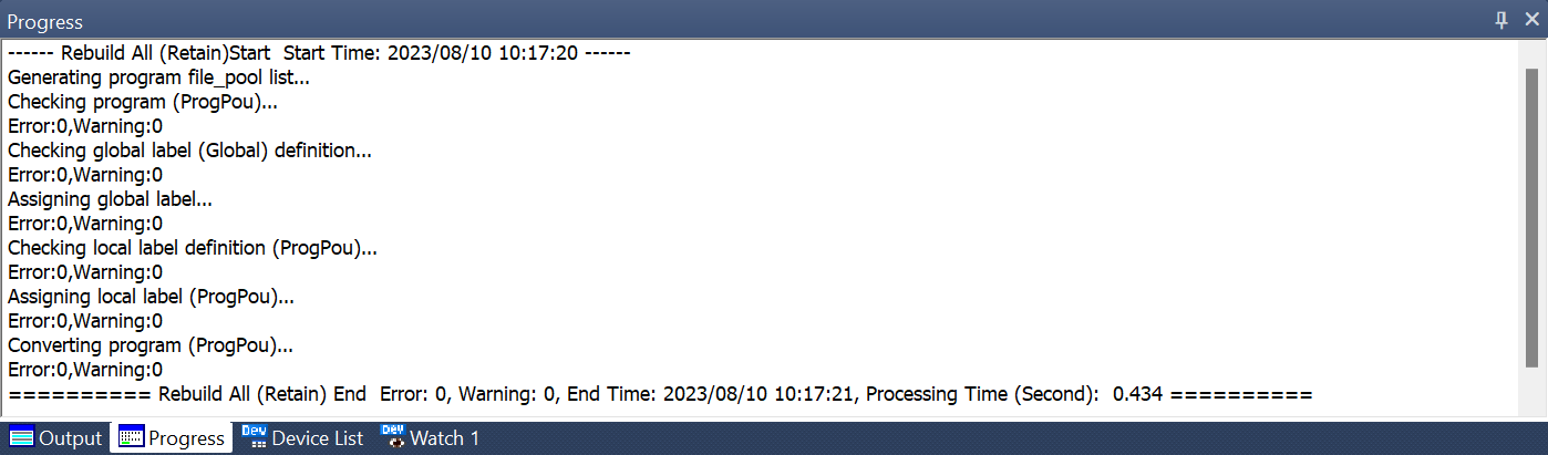
Select Convert → Rebuild All from the menu bar to compile the project.
Check the Progress output console to verify that there are no errors:
Now if no errors are present the project is ready to be downloaded to a PLC or debugged into the simulator.
Step 3 Download the project to the PLC
This step is to download the program to a physical PLC, if you want use the simulator instead jump to Step 4 - Use the GX Simulator 3.
The select Online → Write to PLC... to open the download page:
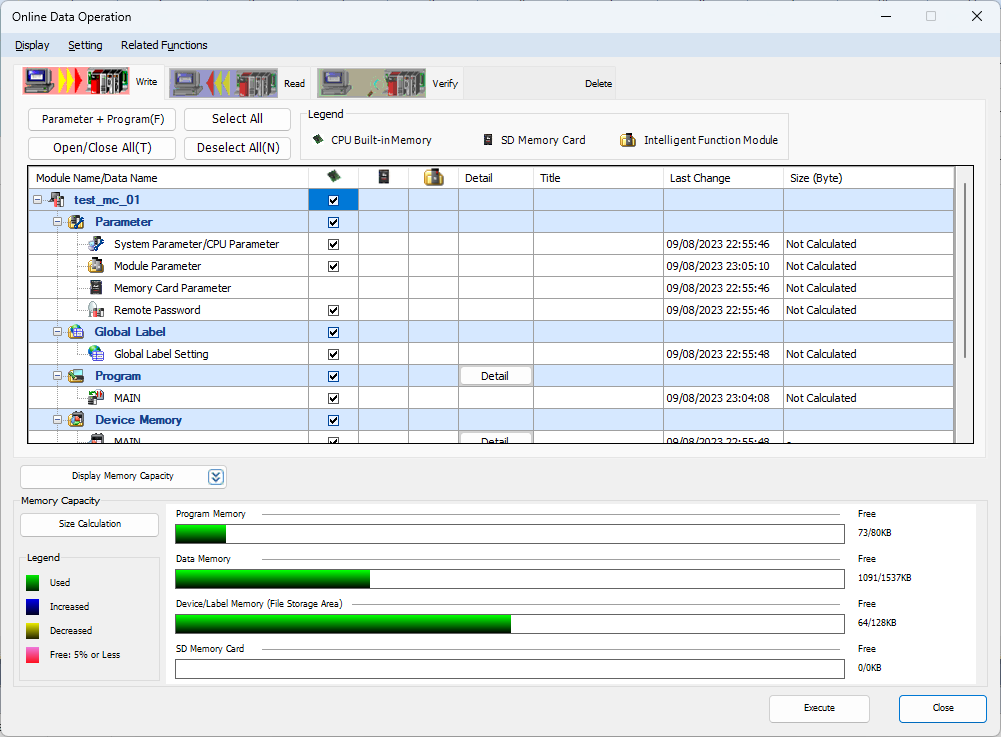
Select the checkbox at topmost level to select everything then press Execute to start download process:
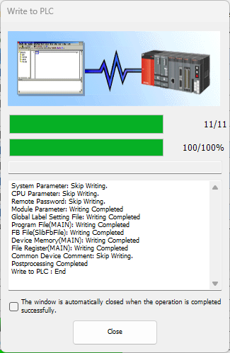
Wait until download process is complete.
Select Online → Remote Operation(S) to check that the PLC has no error and it is running:
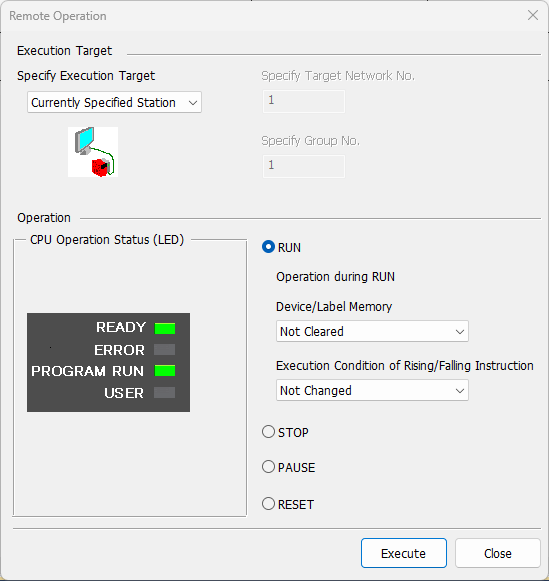
If Program Run led is not green select the RUN radio button and press Execute.
Now the PLC is running and can reached by FlexSim.
Step 4 Use the GX Simulator3
The GX Works3 provide a PLC simulator, called GX Simulator3, that allow to run the program into this virtual environment.
The select Debug → Simulation Write to PLC → Start Simulation will do two actions: launch the simulator and download the program automatically.
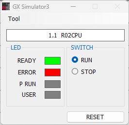
When load the program is dowloaded to the simulator
Wait until download process is complete, after the simulator switch to run mode:
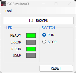
Now the simulator is running and can reached by FlexSim.
Step 5 Configure the MX Component Communication Setting Utility
The Communication Setting Utility allow to create logical stations that define communication protocols and parameters to connect a PLCs or a simulator.Following are the steps to configure two logical stations used in this tutorial:
- A station to connection a iQ-R R02 PLC.
- A station to connection a GX Simulator3 instance.
Run the Communication Setting Utility with administrator privileges:
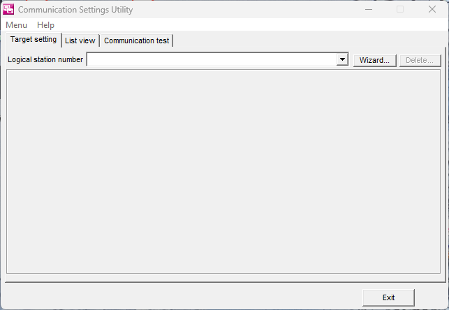
Press the Wizard.. button, the Introduction page will open:
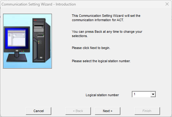
Write 1 into the Logical Station Number field an press Next> button, the PC Side will shown:
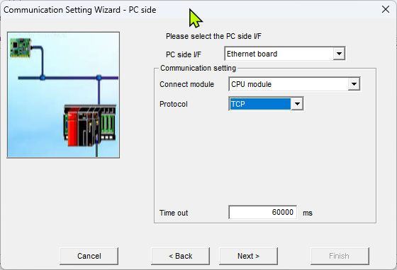
- PC side I/F - Select Ethernet board.
- Connect module - Select CPU Module. The embedded PLC Ethernet interface will be used.
- Protocol - Select TCP. This is not mandatory, also UDP can be used.
- Time out - Leave the default value of 60000.
Press the Next> button, the PLC Side page will shown:
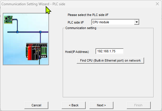
Write the IP address of the PLC into the Host(IP Address)
field an press Next.
The Network will appear.
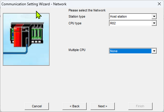
- Station Type - Select Host station.
- CPU Type - Select R02 from the list of supported CPUs.
- Multiple CPU - Leave None.
Press the Next> button, the Finished page will shown:
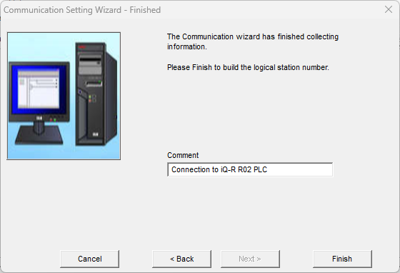
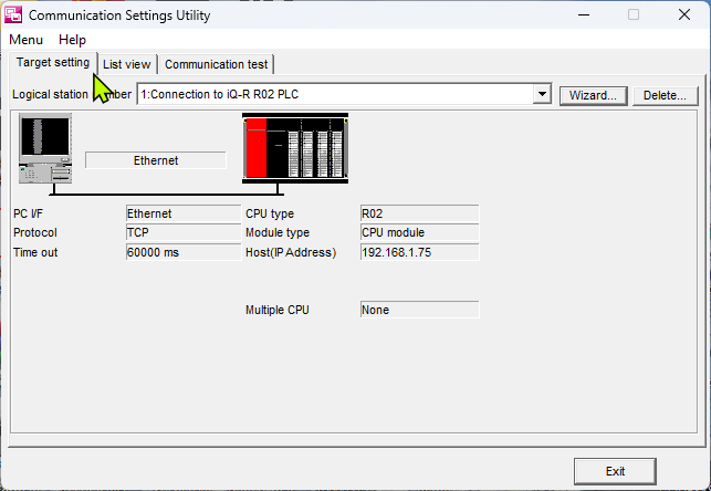
Now the logical station no. 1 is configured and can be used to connect the
configured PLC.
Following are the steps to define a logical station that connect a GX
Simulator 3 instance.
Now press again the Wizard... button to add another
station, below are the parameters to use:
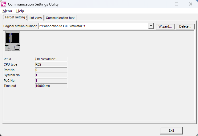
- Introduction page:
- Logical station number - set to 2.
- PC Side page:
- PC side I/F - Select GX Simulator 3.
- CPU Type - Select R02.
- Set Port No., System No., PLC No, Time out. - Leave default values.
- Finished page:
- Comment - Write a description text.
Now the logical station no. 2 is configured and can be used to connect the simulator:
Use the Communication Test tab to verify the
connection of the created logical stations.
Step 6 Prepare a FlexSim model
Prepare a FlexSim model to connect to the device.The model that we will use for this tutorial represents a really simple production system where a box item is packaged into a tote:
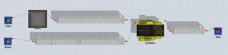
Build a model with two sources (one for boxes and one for totes), a queue for totes and a combiner that will join boxes and totes.>
Connect the elements with conveyors, as represented in the figure above and set conveyor speed to 0.5 m/s.
Rename the sources to “Boxes” and “Totes”: Totes source is configured to produce 100 totes at time 0, Boxes source is configured to produce a box every 10s.>
A photo-eye is placed on boxes conveyor, approximately 1 meter before totes conveyor start.
Combiner puts a box into a tote in 5 seconds.
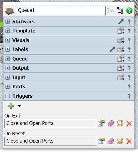
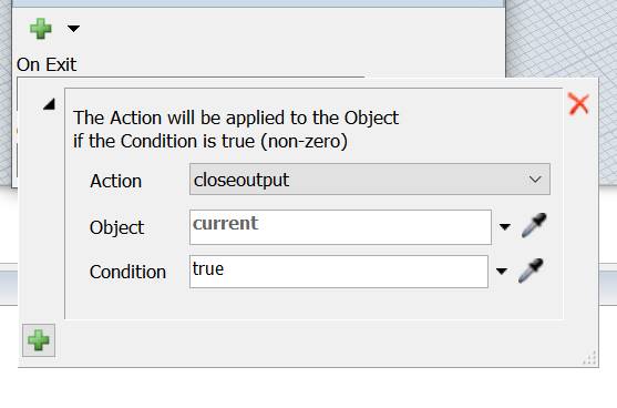
At last, configure the queue to close its outputs at reset and every time that a tote exits from it.
Step 7 Test the model
At first, we will create a Mitsubishi MC Connection to connect our model directly with the PLC.
On FlexSim, create a new Mitsubishi MC Connection by adding a new Emulation/Connection from the Tools menu.
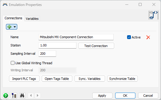
Insert the Station Number (according to the configured logical stations) then press “Test Connection” button: if everything is all right you should see a detailed message.
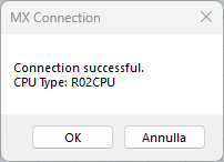
If the connection is successful it's possible to create the Control and Sensor variable to connect the PLC tags.
From the menu add a Mitsubishi MX Component Sensor and Mitsubishi
MX Component Control variables.
menu add a Mitsubishi MX Component Sensor and Mitsubishi
MX Component Control variables.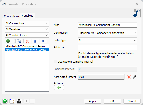
Now, it’s necessary to define how FlexSim models drives PLC input and how PLC’s output is managed by FlexSim as well.
In our model we want that – when a box covers the photoeye – the PLC input is set to 1 and when the PLC output is set to 1 a tote is released from its queue.
The PLC input should be reset to 0 when the photoeye is clear.
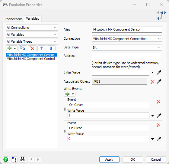
To do this, select the Mitsubishi
MX Component Sensor, set the Data Type to Bool and
set the Address to X0.
Then associate it to the photoeye and configure it to write values 1 and
0 when the photoeye is covered and cleared.
Also set the initial value to 0 to reset the PLC input at model reset:
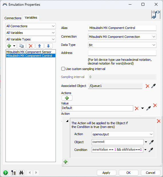
Now select the output variable and associate it to the Tote queue.
To do this, select the Mitsubishi MX Component Control, set the Data Type to Bool and set the Address to Y0.
Then configure a new action and set the queue open its output when the PLC value turns from 0 (oldValue) to 1 (newValue):
Now the model is fully configured and can be reset and run.
Remember to set the FlexSim’s run speed to 1 to match the timing of the PLC.
You should see a tote exiting the queue 1 second after a box covers the photoeye.